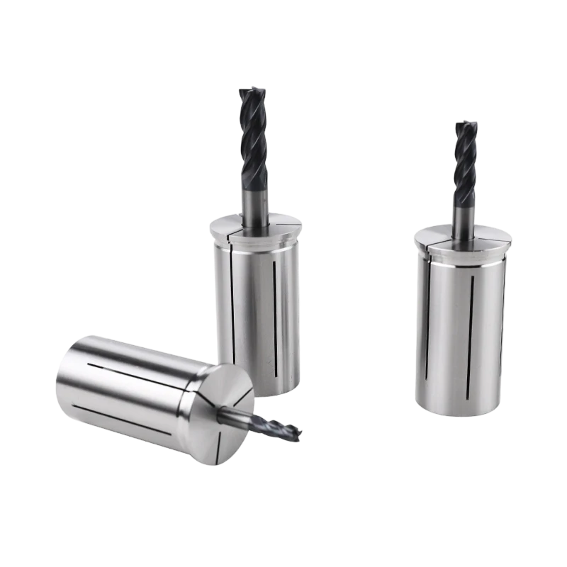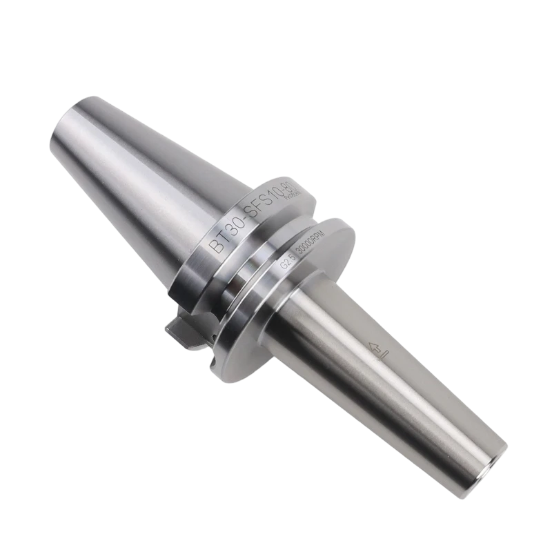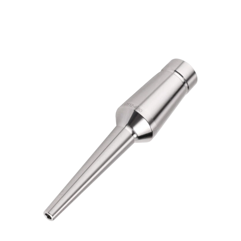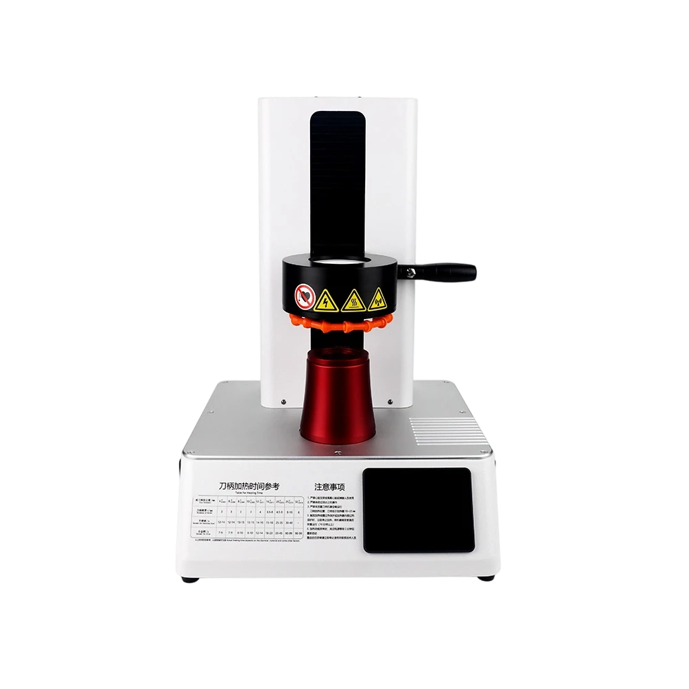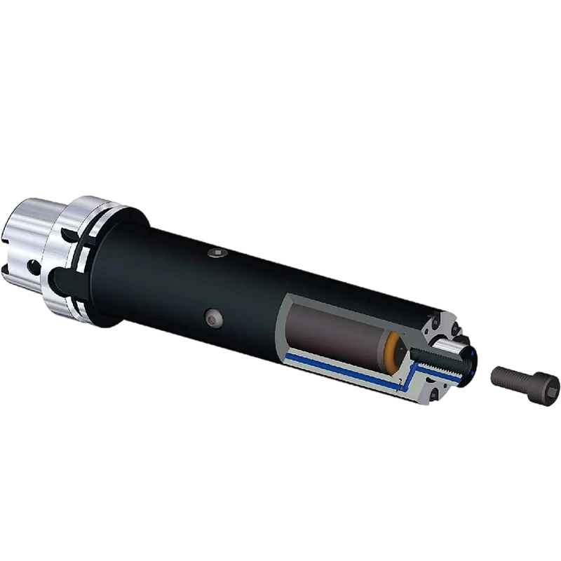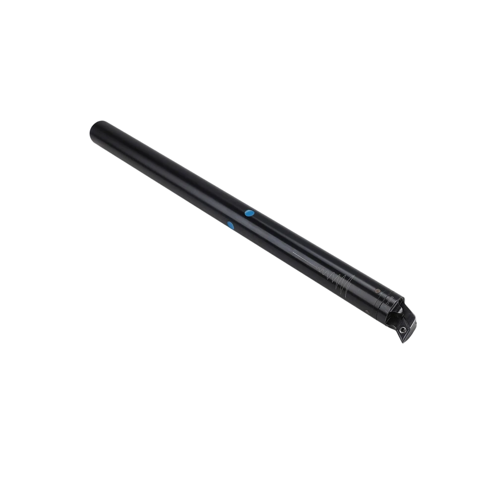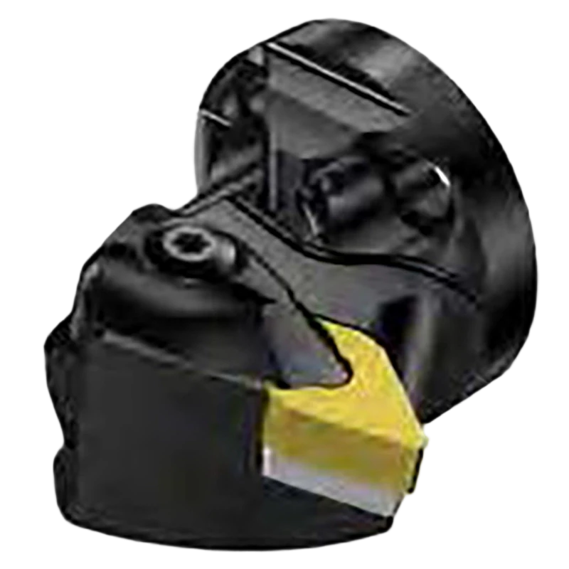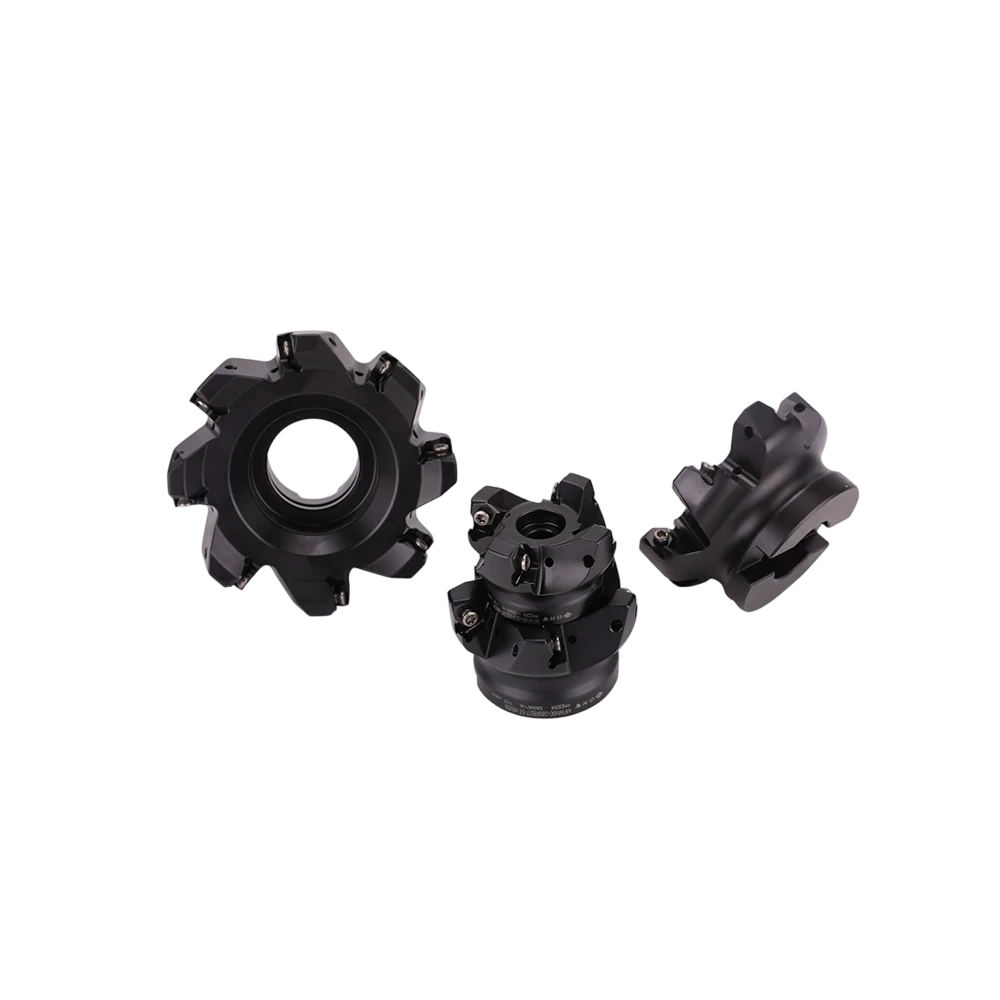


Deep bores, pockets, and intersecting passages can turn a routine setup into a problem of tool clearance, chatter, poor finish, or a part that moves under cutting load. For CNC Tooling for Energy Equipment Manufacturing, plan tool reach for deep cavities and the clamping strategy for energy components together: check the actual access path, workholding rigidity, tool overhang, and chip evacuation before cutting. This guide uses practical deep-feature machining, vibration control, and professional concepts such as L/D ratio, static stiffness, and regenerative chatter to help you build a setup you can verify at the machine.
Evidence note: No auditable customer record or source was provided for this article, so it does not present an invented shop-floor story, named customer, or claimed production result. The worked planning method below is a reproducible engineering workflow, not a report of a measured customer outcome.
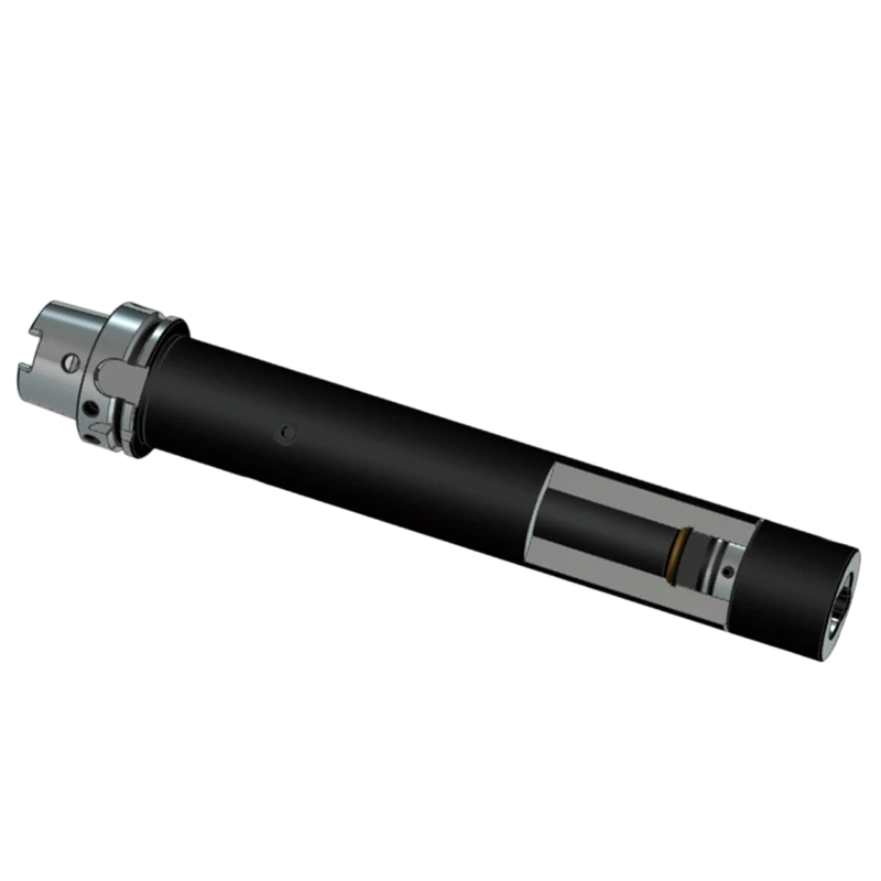
Energy components such as pump casings, valve bodies, compressor housings, and turbine-related parts may combine long-reach features with sealing faces, thin walls, intersecting holes, or restricted tool entry. The drawing and process plan—not the part category alone—determine the correct approach. Before choosing an extended tool or adding clamps, answer four questions:
- Can the cutter reach the full feature? Include the holder, spindle nose, approach motion, and required clearance—not only the cutting edge.
- Can the tool cut stably at that reach? Assess overhang, tool construction, holder interface, runout, and cutting load.
- Can the workpiece resist the load? Support the part near the machining zone without distorting it or blocking the tool path.
- Can chips and coolant leave the feature? A tool that physically reaches the bottom may still recut chips or lose effective cooling.
Keep drawing tolerances and the machine and tool manufacturers’ limits as controlling requirements. General rules of thumb are screening tools, not substitutes for the specified process, a trial cut, or a qualified engineering review.
CNC Tooling for Energy Equipment Manufacturing: What to Resolve Before Setup
Preparation for Deep-Feature Tool Reach Planning
- Part information: current drawing and model, material and condition, feature depth and width, bottom geometry, tolerance, surface-finish requirement, datum scheme, and any thin-wall or distortion concerns.
- Machine information: spindle and holder interface, usable tool length, axis travel, work envelope, tool-change clearance, coolant delivery, and any limits in the machine manual.
- Tool information: cutter diameter and cutting length, neck and shank dimensions, overall length, holder gauge length, recommended operating range, and manufacturer cutting data for the material.
- Workholding: vise, fixture, soft jaws, locating features, support points, clamps, suitable fasteners, and a method to inspect the part after clamping.
- Measurement and verification: calipers or micrometers as appropriate, an indicator and suitable holder, a probe if available, setup sheet, and a safe method for checking clearances.
- Safety controls: machine guarding, approved lifting and handling procedures for heavy components, safe tool-change practice, and the machine builder’s rules for dry runs and single-block operation.
Record the coordinate system, tool assembly, clamp locations, and inspection points in the setup documentation. If material, machine, holder, or tooling data are missing, stop and obtain them rather than filling the gap with assumed cutting values.
Information and equipment for CNC Tooling for Energy Equipment Manufacturing
-
Step-by-Step: Tool Reach and Clamping for Deep Features
Tools: part drawing or CAD model, feature list, and a machine or CAM setup view.
Action: Identify the deepest cutting point, entry direction, side-wall clearance, bottom shape, and any intersecting features. Check the complete approach and retract path, including the tool holder and spindle nose. Note surfaces that must not be contacted and the datums used to locate the part.
Parameters: Use the drawing’s dimensions and tolerances. Record feature depth, opening size, cutter access direction, and the clearance needed for the selected tool assembly. Do not infer an unlisted tolerance from the model display.
Check: Simulate or otherwise verify the full tool assembly through the approach, cutting, and retract motions. Confirm that the holder clears the opening and that the planned path does not cross clamps or protected surfaces.
If it fails: Change the approach direction, operation order, fixture orientation, or tool assembly. If the model or drawing does not define a required clearance, resolve it with engineering before machining.
-
Step 1 — Map the feature and access path
Tools: tool and holder drawings, toolmaker data, and a reach worksheet.
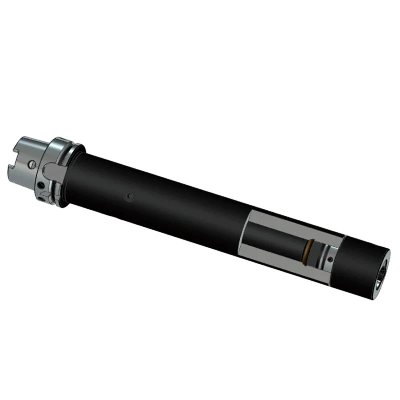
Action: Calculate the minimum assembled reach from the holder gauge line to the farthest cutting point, then add only the approach and clearance required by the operation. Compare that requirement with the cutting length, neck length, shank, and holder dimensions. Calculate the overhang-to-diameter ratio (L/D) using the relevant unsupported length and cutter diameter; state clearly which length is being used.
Parameters: Use the toolmaker’s permitted overhang, speed, feed, and application guidance for the exact tool construction. L/D is a screening measure, not a universal pass/fail limit. A simplified cantilever model shows why reach matters: for an idealized round beam under the same end load and material assumptions, bending deflection varies with unsupported length cubed and inversely with diameter to the fourth power. Real cutting tools, holders, flutes, and intermittent cutting are more complex, so this relationship explains sensitivity but does not predict finished-part error by itself.
Check: Verify that the cutting edge reaches the feature while the holder remains clear, and that the selected assembly is within manufacturer guidance. Confirm the tool’s actual assembled length at the machine.
If it fails: Consider a larger-diameter cutter if the opening allows it, a shorter holder or extension, a different tool construction, another setup orientation, or staged machining. Do not extend a tool beyond its documented limits simply to avoid a setup change.
-
Step 2 — Calculate the required reach and screen tool rigidity
Tools: fixture model or sketch, clamps and supports, fastener specifications, and the part’s datum scheme.
Action: Locate the part from defined datums and support it close to the cutting zone where practical. Arrange clamps to resist the expected cutting-force direction while keeping the tool path, probing points, and chip flow clear. For thin walls or irregular castings, use suitable supports and avoid forcing the part into alignment with excessive clamp load.
Parameters: Follow fixture and fastener ratings, the workholding manufacturer’s instructions, and the approved process for the material and component. There is no reliable universal clamp-torque value for all energy components: thread condition, lubrication, fastener size, fixture geometry, and part stiffness all affect the result. Specify torque only when the engineering or fixture documentation supports it.
Check: Confirm that the part seats on its locators, that supports contact as intended, and that clamps cannot collide with the tool or holder. Probe or indicate the relevant datums before and after clamping to detect movement or distortion.
If it fails: Clean and inspect locating surfaces, correct the support height, revise clamp placement, or redesign the fixture. If clamping shifts a datum or changes a critical wall dimension, do not compensate blindly in the CNC program; determine whether the fixture or clamping sequence is deforming the part.
-
Step 3 — Design a rigid, non-distorting clamping arrangement
Tools: toolmaker recommendations, CAM software or a reviewed manual toolpath, coolant or air system suited to the operation, and chip-clearance provisions.
Action: Select an operation that suits the feature and tool: for example, a suitable roughing strategy followed by a controlled finishing pass where the geometry permits. Plan how chips will exit a deep pocket or bore. Confirm that coolant delivery, air, or a chip-breaking strategy is appropriate for the material, machine, and cutting tool.
Parameters: Set speed, feed, engagement, and stepdown from the toolmaker’s data for the actual material, tool diameter, reach, and machine conditions. Apply any long-reach adjustments only in line with that guidance and a validated process. Do not copy a cutting speed from a different alloy, tool grade, or setup.
Check: Review the toolpath for full-depth engagement, abrupt load changes, trapped-chip locations, and safe retracts. Confirm that the coolant or chip-removal method reaches the cutting zone and that the machine can execute the programmed motion.
If it fails: Revise the path or operation order, improve chip evacuation, or choose a tool and setup better suited to the reach. If chips are recut or the sound and load indicate instability, pause and diagnose rather than increasing feed or speed without evidence.
-
Step 4 — Choose the cutting approach and chip-control plan
Tools: assembled cutter and holder, indicator or suitable tool-measuring equipment, tool list, and machine setup documentation.
Action: Clean and assemble the holder and tool according to their manufacturers’ instructions. Measure or verify tool length and, where the process requires it, runout near the cutting portion. Load the correct tool data and confirm that the offsets correspond to the installed assembly.
Parameters: Use the toolmaker’s runout and assembly requirements and the machine’s prescribed measurement method. Record actual tool length and any required runout reading; do not substitute an assumed value for a measurement.
Check: Confirm tool identity, assembly security, offset, reach, and clearance. With the machine in a safe state and using approved procedures, verify the program’s approach and retract motions before cutting.
If it fails: Clean and reseat the tool, inspect the holder and cutting tool for damage, correct the tool data, or replace components that do not meet their specifications. Repeat the clearance and measurement checks after any change.
-
Step 5 — Verify tool assembly, runout, and machine clearance
Tools: approved dry-run or single-block procedure, suitable measuring instruments, inspection plan, and setup log.
Action: Run the program using the machine builder’s safe prove-out procedure. Where appropriate, use reduced rapid motion and single-block execution to verify the path, while maintaining required guarding and safe distance. Make a controlled first cut, then inspect the feature and the part’s datums before continuing with production.
Parameters: Use the approved program revision, tool offsets, cutting data, and inspection method. Compare measurements with the drawing’s stated tolerances and inspection plan; record the actual readings rather than describing a result as “good.”
Check: Look for dimensional drift, visible chatter marks, unexpected tool wear, chip packing, witness marks from a collision risk, or movement in the workpiece. Confirm critical dimensions and surface requirements with the specified inspection method.
If it fails: Stop the cycle and identify whether the cause is tool deflection, workpiece movement, tool runout, chip recutting, offset error, or an incorrect process assumption. Change one controlled variable at a time, document the change, and reinspect before releasing the operation.
Step 6 — Prove out the operation and inspect the feature
Common Deep-Feature Machining Errors and Practical Fixes
| Problem | Likely cause | Practical response |
|---|---|---|
| Chatter or poor finish at depth | Excessive unsupported reach, runout, unstable engagement, or insufficient workpiece support | Measure the tool assembly and runout, reassess L/D and cutting engagement, check clamping, and compare the process with toolmaker guidance. Change one factor at a time. |
| Holder or spindle-nose interference | Reach was calculated from cutter length alone | Recheck the complete assembly and simulate approach and retract paths with the holder and spindle geometry included. |
| Part moves or a thin wall changes dimension | Locators are dirty, support is poor, or clamping distorts the component | Clean and inspect datums, improve support, revise the clamp sequence, and compare measurements before and after clamping. |
| Tool breaks or chips pack in the feature | Chip evacuation is inadequate, cutting data do not suit the setup, or the tool is outside its application limits | Stop and inspect the tool and feature. Review coolant or air delivery, path, engagement, and manufacturer recommendations before restarting. |
| Feature is out of position after reclamping | Setup datums or locating method changed between operations | Reconcile the datum scheme, fixture location, and probing routine. Update the setup documentation only after the cause is understood. |
How to Document a Verified Shop-Floor Case
A useful case study should let another machinist distinguish measured results from opinion. Record the component and material only as permitted by the customer, the feature geometry and tolerance, machine and tool assembly, tool overhang and diameter, holder, fixture and clamp arrangement, cutting data source, inspection method, actual before-and-after measurements, and any relevant production conditions. Preserve the inspection record and identify who approved the process. Do not publish a cycle-time reduction, tool-life gain, or scrap-rate change unless records support the comparison and the baseline is defined.
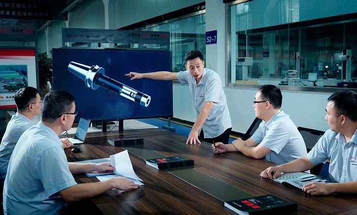
This article does not claim that Ounuowei or a named customer achieved a particular result. The image is provided as a setup-planning visual; it is not evidence of a measured machining outcome. That distinction keeps practical guidance separate from a verified case history.
Final Checklist for CNC Tooling for Energy Equipment Manufacturing
- Feature depth, access direction, datum scheme, and drawing requirements are confirmed.
- Reach includes the full tool assembly, approach, retract, and holder clearance.
- L/D and tool rigidity have been screened against the toolmaker’s application guidance.
- Clamps and supports resist cutting loads without blocking access or distorting the component.
- Tool identity, assembly, offset, and required runout checks are documented.
- Cutting data and chip-control methods match the actual tool, material, machine, and operation.
- The path is proved out safely, and critical features are inspected with the specified method.
- Any change is recorded, checked, and approved before the process is released.
Reliable deep-feature work comes from treating tool reach, clamping, chip evacuation, and inspection as one machining plan—not as separate fixes after a problem appears. Use the part drawing and manufacturer data to set the limits, verify the complete setup at the machine, and document measured results. For CNC Tooling for Energy Equipment Manufacturing, that disciplined approach to tool reach planning for deep cavities, clamping strategy for energy components, deep-feature machining, vibration control, L/D ratio, static stiffness, and chatter provides a sound basis for repeatable decisions. This Ounuowei guide offers a planning method, not a substitute for component-specific engineering approval.